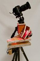
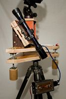
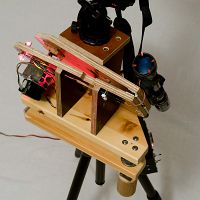
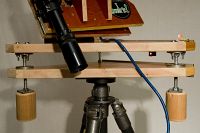
2010-10-15 - Camera Mount for Night Sky Photography
thumbs/DSC_2308.jpg
Despite efforts to make the camera mount as sturdy as possible, the camera mounted high above the tripod can easily shake a little if there is wind, vibrations in the ground or if someone touches the tripod or camera mount. It is therefore necessary to avoid such vibrations as much as possible to get good results.
thumbs/DSC_2315_DSC_2322.jpg
The hinge and the scope have to be very well aligned to make sure the hinge points to the North Star when the cross hair of the scope is centered on the star.
thumbs/DSC_2316.jpg
There are four faintly lit LEDs shining on the front lens of the scope to provide some backlighting to make the cross hair visible when looking at the essentially black sky. The LEDs have to be very faint since otherwise they would swamp the light from the North Star.
thumbs/DSC_2320.jpg
The two base plates, the adjustment screws (to the left and to the right) and the pivot (far away in the middle). To point the hinge towards the North Star, one first makes a coarse adjustment by extending or contracting the legs of the tripod and turning it to make the scope point as well as possible towars the star. One then adjusts the screws to make the cross hair fall directly on the star. The red backlight of the cross hair is bright enough to make many fainter stars hard to see. This minimizes the risk of aiming at the wrong star, which can otherwise be a problem due to the narrow field of view that the scope offers.
thumbs/DSC_2320_DSC_2319.jpg
Each adjustment screw runs through a threaded metal plate bolted to the bottom base plate while it is swiveled in a metal plate attached to the top base plate. A large wooden handle on the screw makes it easy to turn it with high precision. After re-aiming the camera it may be necessary to realign towards the North Star since things may have inadvertenltly moved a bit.
thumbs/DSC_2321.jpg
The electronics box with the control panel mounted on one of the tripod legs. The controls from the left to the right are: LED lights on/off; run motor to allow photography; LED that flashes when the motor is running; power LED; run motor fast to reset to original position; run motor fast in other direction. Inside the box there is a crystal controlled microcontroller and drive electronics for the motor.
thumbs/DSC_2329.jpg
thumbs/DSC_2330.jpg
The aluminum reinforcements along the edges of the base plates are there to make the base plates more rigid. They otherwise tend to flex a bit more in the direction perpendicular to the wood fibers than in the other direction.
thumbs/DSC_2331_DSC_2317.jpg
The stepper motor.


© Per Magnusson
1 2 3
Jalbum 8.0